Skip to content
Products
All
Laser Diode Controllers
Time & Frequency
SK-Series Modular Instruments
Platforms
Obsolete Products
Pricing & Ordering
Price List
Getting a Quote
Ordering Information
Contact
Toggle website search
Menu
Close
Products
All
Laser Diode Controllers
Time & Frequency
SK-Series Modular Instruments
Platforms
Obsolete Products
Pricing & Ordering
Price List
Getting a Quote
Ordering Information
Contact
Toggle website search
Sisyph designs instruments for quantum technologies and Time/Frequency applications
Sisyph Products
New Products
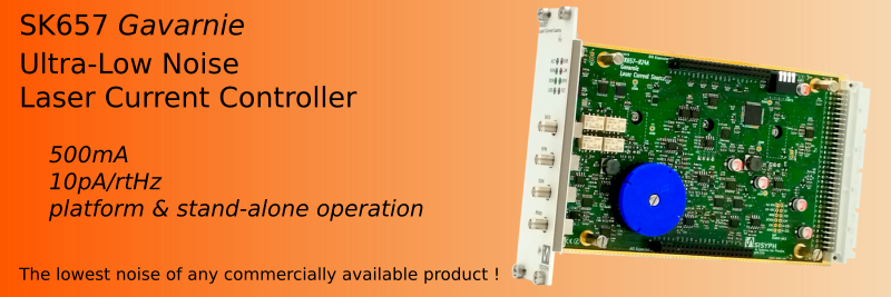
Laser Diode Controllers
Time & Frequency
SK-Series Instruments
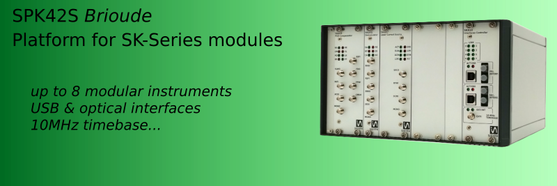
Platforms
Obsolete Products
Quote
Price List